kicad:kicad_spice_quick_guide
This is an old revision of the document!
Table of Contents
Quick Guide to using KiCad for SPICE simulation
What you'll need
You will need the following:
- A SPICE engine
- ngspice: Arguably the most FOSSy commonly available SPICE engine.
- gnucap: Not actually SPICE but tries to be syntax-compatible.
- SpiceOpus: Proprietary but nice, especially the output plotting.
- PSpice: Windows-only, expensive, defacto standard professional solution in the USA. They also have a tradition of making available a gratis crippleware student version. Also has a a GUI, so …
- Component librar(ies) with SPICE symbols
- There is a library of basic SPICE components that ships with KiCad. It's good enough for initial experimentation.
- In Debian-based Linux (and likely others), it's at
/usr/share/kicad/library/pspice.lib. (PSpice is a popular proprietary version of SPICE.) - EESchema does not include this library in projects by default.
- I am maintaining (slowly) my own library of components based on the above with some changes and additions.
Configuring a project
- Create a new project in the conventional way.
- Open EESchema and remove all the library references included by default.
- Manually add one or more libraries with SPICE components to the project.
- The SPICE library that comes packaged with KiCad is not in the set of default libraries included in new KiCad projects.
- Specify the SPICE engine you want to use.
- Click the “Generate netlist” button (or the equivalent menu item).
- Select the “Spice” tab and enter the name of the command to invoke the simulator (with or without path) in the “Simulator command:” textbox.
Making it happen
- Do your schematic capture, subject to a couple best practices:
- For named nets, use global labels instead of local labels.
- In the netlists, global identifiers will be used as-is. However, local labels will get text prepended to the name, and this will make it hard for you to remember/guess what the full identifier is.
- Use the “
0” component from a SPICE component library rather than theGNDsymbol.- “
0” is the official name of ground node in SPICE. Some engines may translateGNDinto0, some are not.
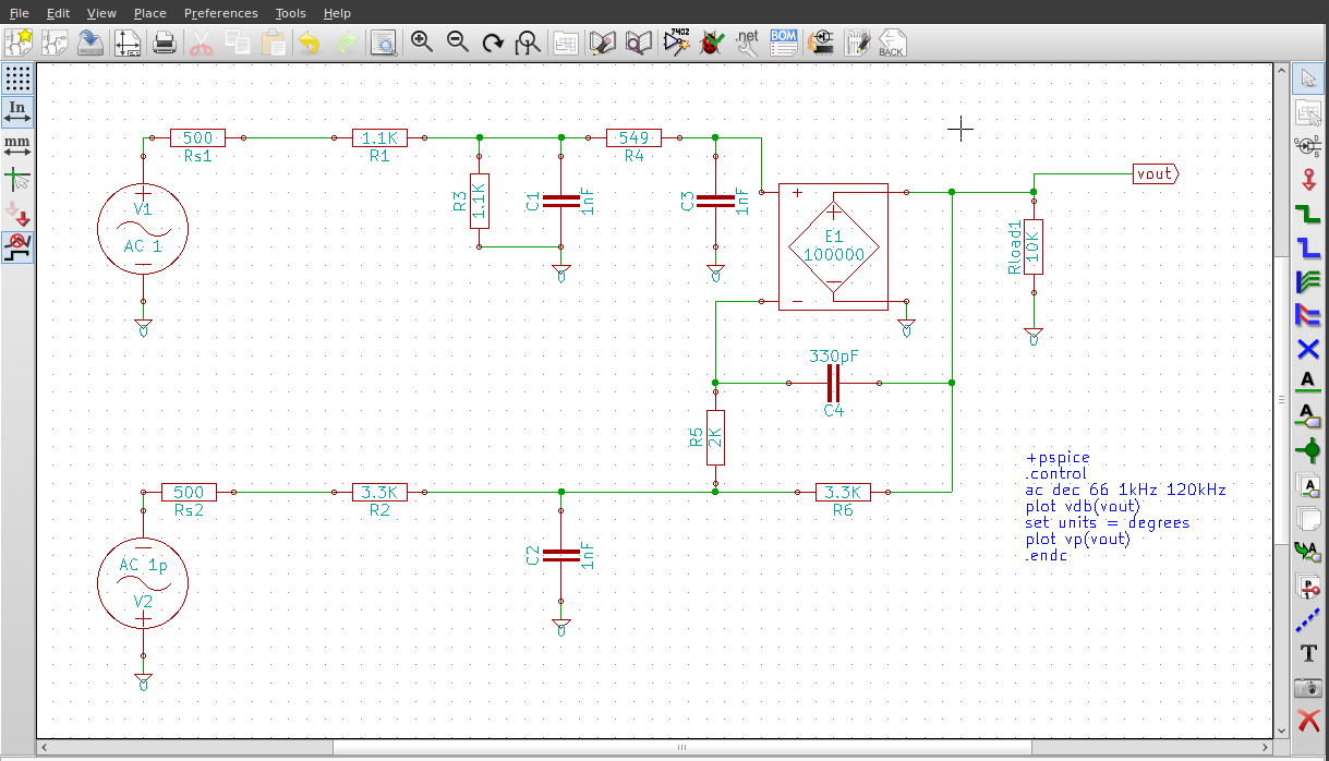
- Specify the simulations you want to run and the output you want to display by adding a text block (i.e., “comment”) with the needed SPICE syntax plus a little added mojo. To do an AC analysis and plot the response at node
vout, you would add the following block:+pspice .control ac dec 66 1kHz 120kHz plot vdb(vout) set units = degrees plot vp(vout) .endc
- The line
+pspiceis KiCad-speak for, “Stick the following text at the end of a SPICE netlist.” There appears to be a bug in the parser that requires you to add a space after
 +pspiceand the line break.
- There is a corresponding
-pspicethat is KiCad-speak for, “Stick the following text at the start of a SPICE netlist.” - If you don't like seeing
pspicein your designs, you can usegnucapinstead. I believe they are exact synonyms in this context, but I am not certain. - Yes, this means you need to learn some SPICE syntax. It's not hard.
- Run the simulation:
- Click the “Generate netlist” button (or the equivalent menu item).
- Select the “Spice” tab, and make sure “Default format” is checked. (You should only have to do this once; it will just save you time in subsequent invocations of the dialog.)
- Click the “Run simulator” button.
kicad/kicad_spice_quick_guide.1348434754.txt.gz · Last modified: 2012/09/23 21:12 by mithat